6502
The MOS Technologies 6502 processor was introduced in the mid-1970s to fill the need for a affordable general-purpose CPU. Its low cost (US$25 at introduction, less than C$0.89 now) was less than one-sixth of competing CPUs, and it had very simple circuitry requirements which made it simple and inexpensive to incorporate it into products. The 6502 (or a slight variation) was therefore used in many home and personal computers, such as the Apple II; the Commodore PET, Vic-20, and C64; the Atari 400 and 800; the BBC Micro; and games such as the Nintendo Entertainment System (NES), Atari 5200, and Atari 6200. A number of variations of this processor have been produced, using different semiconductor processes, integrated peripherals, instruction and data-width extensions, and pinouts. Several different versions are still in production for various embedded applications, and it remains a popular chip for homebrew system builders.
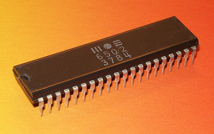
The MOS 6502 processor. Image credit: Christian Bassow - CC-BY-SA 4.0
Hex notation - $XX: In most 6502 documentation, including this page, the $ prefix indicates hexadecimal notation. On other systems, this may be designated by a 0x prefix.
Memory
The 6502 is an 8-bit processor with a 16-bit address bus. It is therefore able to access 64 kilobytes ( bytes). Since each 16-bit address is comprised of two 8-bit bytes, memory can be viewed as 256 pages of 256 bytes each.
Each pointer in memory is stored in two consecutive memory locations, with the lowest-value byte stored first; this is known as Little Endian order. Thus, a pointer at memory location $0010, which points to memory location $ABCD, would be stored like this:
 Memory $0010: $CD
 Memory $0011: $AB
Some pages have special, pre-defined purposes:
| Page | Name | Starting address | Ending address | Purpose |
|---|---|---|---|---|
| 00 | Zero Page | $0000 | $00FF | Variables requiring fast access |
| 01 | Stack | $0100 | $01FF | Values are pushed to, and pulled (popped) from, this region in first-in last-out (FILO) order. The stack descends as it is used - more recently-pushed values are stored at lower addresses than older values. The stack wraps around, so if more than 256 bytes are pushed, the oldest values will be overwritten. |
| FF | Vector Table | $FF00 | $FFFF | The last 6 bytes of this page contain three 2-byte addresses. $FE contains a pointer to code which is run when an interrupt request is received; $FC contains a pointer to code which is run when the CPU is reset (including when it is first started); and $FA contains a pointer to code which is run when a non-maskable interrupt (NMI) is received. (Note that the 6502 BRK instruction is counted as an NMI, and the B status flag can be used to determine if a hardware NMI or BRK instruction was received). |
In addition, each system built using the 6502 would have hardware devices, such as the video system, keyboard, and communication interfaces, occupying a portion of the address space.
Registers
There are three general-purpose registers:
- Accumulator (A) - the main register for math operations.
- X Index (X) - a register which can be used for limited math operations as well as indexed addressing modes, where an index value is added to a base address for memory operations.
- Y Index (Y) - a register similar to the X register. Some index operations may only be performed with a specific index register (X or Y, but not interchangeably).
There are also three special-purpose registers:
- Program Counter (PC) - a pointer to the currently-executing instruction in memory.
- Stack Pointer (S or SP) - a pointer to the current position in the stack
- Processor Status (P or PS) - a collection of bits (flags) which indicate or control aspects of the processor mode and status:
- C - Carry - Used to carry or borrow during addition and subtraction operations. If set (=1) at the start of an add-with-carry (ADC) operation, an additional 1 will be added to the result; if cleared (=0) at the start of a subtract-with-carry instruction (SBC), an additional 1 will be subtracted from the result. This flag will be set or cleared to indicate if an (unsigned) addition overflowed (result > 255) or the (unsigned) subtraction underflowed (result < 0)
- Z - Zero flag - indicates that an operation produced a zero result. Since comparison instructions (CMP, CPX, CPY for comparisions involving the A, X, or Y registers respectively) are actually subtractions, comparing two equal numbers by subtraction will result in a zero value, setting this flag.
- I - Interrupt disable
- D - Decimal mode - bytes are interpreted as two-digit decimal values instead of 8-bit binary values when doing math
- B - Break - Indicates a software interrupt (BRK instruction) has caused a non-maskable interrupt (NMI), rather than a hardware NMI.
- V - Overflow - Set when a math operation overflows (result > 127) or underflows (result < -128) a one-byte signed result
- N - Negative Sign - set when an operation produces a negative result (bit 7 is set in the result)
Instruction Set
The 6502 instruction set consist of a number of single-byte opcodes, each of which is followed by 0, 1, or 2 bytes of arguments. Each opcode corresponded to an instruction, which consists of an operation and an addressing mode. 6502 Assembly Language uses 3-letter menomics to specify the operation, and argument syntax to specify the addressing mode. For example:
 LDA #$05  ; load the accumulator with the number 5
 LDA $05   ; load the accumulator with the contents of memory location $05 in the zero page ($0005)
 LDA $f005 ; load the accumulator with the contents of memory location $f005
See the references (below) for the full details of the 6502 instruction set.
6502 Emulator
Since 6502 systems are no longer very common, a web-based 6502 Emulator is available for assembling, testing, and debugging 6502 Assembly code.
Resources
- 6502.cdot.systems, the 6502 emulator we use in this course
- Wikipedia entry for 6502
- 6502.org
- Visual 6502 - a project to physically disassemble and analyze the 6502 chip, including photographs of the chip die and a visual simulation of voltages on the chip
- Easy 6502 (tutorial using an earlier version of the 6502 emulator we use in this course)
- 6502 Opcodes with Register Definitions
- 6502 Opcodes with Detailed Operation Information
- MOnSter 6502 - a large-scale, transistor-level implementation of the 6502, with lots of LEDs!